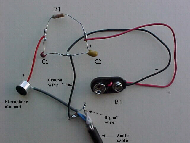
This picture shows the components connected without use of a circuit board. The microphone element does not get connected to the circuit until it has been mounted on a dinner plate. It is shown connected here for the purpose of illustrating the complete circuit. The audio cable shown is the brand called Canare L-4E6S. This cable has five conductors - two that are blue, two that are white, and one is a braided shield. First, the two white wires and the the two blue wires get twisted together to make two twisted pairs. Then, the braided shield and one of the twisted pairs are connected. The result is a two conductor cable. In the configuration above, the white twisted pair is used to conduct the signal; the blue twisted pair (combined with the shield) are connected to ground. The black ground wire labeled in the picture is an optional wire (~ 24-26 gauge) that is added to facilitate the necessary connection to ground at the juncture of the two capacitors.
It is important to note that there are three components where the polarity must be considered. These are the microphone element, the battery snap-on connector above (has red positive and black negative wires), and the C2 capacitor, which has a small + sign on the positive terminal -- this side gets connected to the positive terminal of the battery.
Warning: If the positive terminal of the capacitor C2 is connected accidentally to the negative terminal of the battery, it will typically burn up within 24 hours, if not immediately. The chances of a fire are slim, but if this capacitor is in contact with flammable material a fire is certainly possible. As a precaution, when the circuit is built, it is a good idea to wrap a layer of black electrical tape around the circuit. This tape is made out of fire-resistant vinyl. This tape also will prevent the electrical components from coming into contact with one another and shorting the circuit.