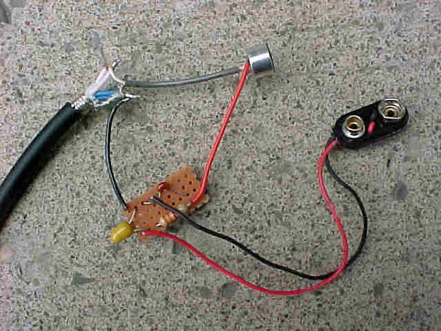
The picture above shows how the circuit might look if a piece of circuit board is used to help organize the components, which are soldered together on the back of the board. You can make your own circuit board out of some inflammable, nonconductive material. A doubled up piece of black vinyl electrical tape will work. You can create the hole with a pin or other thin sharp pointed object. Again, in the picture above, the microphone element is included for the purpose of demonstrating the complete circuit. If a Knowles mic element is used, there will be three wires coming from the mic, and they should be connected to the circuit as indicated below.
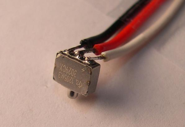
The white wire is connected to the positive post and this wire leads to the junction of R1 (opposite the side where C2 and the battery connect). The middle post (red wire) is the signal and that gets connected directly to the signal wire in the audio cable (which in most cases will be associated with pin 2 in XLR connectors). The left post in the picture (black) wire is the ground wire, which gets connected to the ground terminal in the circuit.